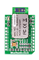
While I was waiting for the Curiosity board to arrive, I started experimenting with my home made Simplicity board (really a PICKit3 Low Pin Count demo board with a microBUS connector soldered in the prototyping area), and I decided to take the Bluetooth Click© out for a spin. What better exercise than writing a wireless boot loader?
Mind there are several different Bluetooth click boards, I got the original one, called simply “Bluetooth Click” and featuring the RN41 module (a product of Microchip Technology, Inc).
Alert: The communication interface and performance of the other modules available might differ significantly and might not work at all with the code presented in this post.
Recently I have worked a bit on boot loaders for the PIC16F1 family, testing different options (high side vs. low side) and different connectivity options, including serial, I2C and USB (see recent post).
The RN41 module, like most other original Roving Networks (hence the RN prefix) modules, has a very simple serial port interface that exposes all of the bluetooth functionality via a simple set of ASCII commands. This is somewhat reminiscent of the AT command set of the modem era.
For those of you who have never known a world without internet or without broadband, my apologies, just ignore the above comment altogether.
Basically the Bluetooth click asks to be connected directly to the UART of a PIC (a PIC16F1709 in my case) at 115,200 baud and from power up appears as available for connection with a Bluetooth Serial Port Profile (SPP) with any device that dares pairing with it.
It follows that the boot loader structure could be borrowed from the Serial bootloader project (mentioned above) with minor adjustments to accommodate the RN41 initialisation.
When a connection is established or lost, the RN41 module sends a notification (a text string) to the PIC. Parsing generic strings from the incoming stream of data can be expensive on a small micro, so borrowing the idea from the Mikroe example files, I decided to make things easy for me by instructing the module to prefix all his notifications with a particular escape character (‘%’). In this way, simply checking its presence and the character following the escape (‘C’ for ‘Connected’ and ‘D’ for ‘Disconnected’ ) I can keep track of the connection state.
The protocol is somewhat inspired once more by the Mikromedia boot loaders also similar to the Clicker boards boot loaders and extensively used by Mikroelektronika in many other tools.
But I had the specific goal to make it fit inside the smallest code protected section of the PIC Flash memory (512 words) without requiring use of assembly! As you will see this effort provided the opportunity to learn two important lessons…
I created the entire set of peripheral configurations (drivers) using the MPLAB Code Configurator in minutes, literally!
I used the MCC to configure the System, GPIO, Timer 0 and EUSART modules. The code generated proved to be tiny (and I did not have to break the data sheet open even once) while I was sure to have all my peripheral settings right first time. It was really nice to have the baud rate calculation done completely automatically and to be able to double check the approximation error (in %) too!
I did not elect to use the MCC Flash Memory configuration though as that introduced a set of functions that turned out to be overkill for my task. A boot loader (like mine) needs only to write to Flash and only in entire rows at a time as it can count on the Loader, the PC application, to do more of the data massaging for it. (Lesson #1)
After a very simple round of tests, I had the loader working but the application size was well over the target 512 words. Much to my puzzlement, a close inspection of the disassembly revealed that large section of the lower 512 words page were still unused, yet there was no apparent way to force the XC8 (rev 1.34) compiler to make use of them. After some fiddling I discovered that the offending section of code (the one spilling over the set memory limit) was one containing literal strings. Removing them from the application, and spelling out those (command) strings char by char did the trick, see the RN41_SetEscape() function in the main.c file. (lesson #2)
A later check with the developers of the MPLAB XC8 compiler confirmed that there is a limitation in the current version (1.34 as of this writing) in where literal string can be located in memory. It will likely be removed in future version making the compiler a bit more agile/efficient when working in such constrained environments (<512).
You can find the entire BlueBoot project source files as git repository on GitHub as part of the Simplicity group of (cross linked) demo projects.
In summary, the blue part of the boot loader proved to be completely abstracted by the excellent service provided by the RN41 module controller. The PIC configuration was spectacularly simple thanks to the MCC tool and the XC8 compiler (once understood) provided a very compact executable to fit in first code protection flash area of the PIC leaving 96% of the device flash memory available for the user application.
P.S. A Loader application called: BlueBoot (written in Python for portability) is provided in the project repository. You can launch it from the command line :
./Blueboot application.hex
Also a simple Blinky test application (compiled with –offset 0x200) is included for convenience.


