
 One thing many of my experiments can often use is an alphanumeric display, even better a graphic one. OLED displays have become really cheap nowadays and their low current consumption (when compared to a TFT display or an LCD with backlighting) makes them an attractive solution. But developing an ad hoc PCB and connecting with the typical flex strip can be quite a challenge for most prototyping needs.
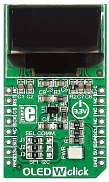
Now it happens that there are no less than three OLED click boards currently listed on the Mikroelektronika catalog: a color model (OLED-C), and two monochrome models, white(OLED-W) and blue (OLED-B). I figured the color version featuring a 96×96 matrix with 16-bit color resolution would be cool, but it would also eat up too much memory ( 96x 96 x 2 = 18,432 bytes) if I was ever to use its full resolution/capabilities. The smaller ( 96x 40) monochromatic displays are just slightly cheaper but most importantly require only 480 bytes to paint a complete picture (96x 40 /8 bytes) something that appeared immediately to be more in tune with the needs and capabilities of my typical small 8-bit application (sensor/driver/controller/node…). I bought myself an OLED W click and started experimenting with it right away.
All OLED displays nowadays feature a smart controller (Chip on Board) that abstracts all the complexity of the actual rows and columns (of pixels) driving as well as keeps a complete image in a local RAM array removing the need to perform constant scanning. The OLED-W click features an SSD1306 controller which presents both an SPI and an I2C interface to the application microcontroller. Both interfaces are also presented on the mikroBUS connector but only the SPI is enabled by default (as in most click boards, a simple 0 ohm resistor can be moved to change selection).
Setting up the project in MPLAB X and configuring a PIC16 microcontroller (PIC16F1709) to use the SPI peripheral (MSSP) in master mode was a matter of a couple of clicks thanks to the MPLAB Code Configurator.
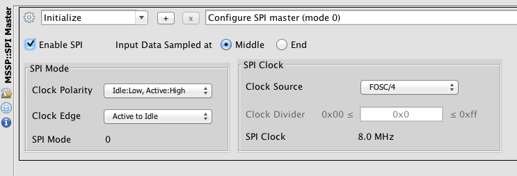
The only detail worth noting in the image above (or button worth clicking…) being the selection of the right Clock Edge. For some reason the MCC seems to prefer the Idle to Active edge ( a.k.a. mode 1) vs. what is in my experience the most frequent case, and surely the case of the SSD1306, that requires an Active to Idle clock edge (mode 0)!
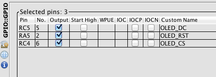
As for the IOs, all I had to do was enabling the standard pin assignments for the SPI port and add three additional pins for the Data/Command register selection (OLED_DC), the device reset (OLED_RST) and chip select (OLED_CS) so to fit the wiring of the board (Simplicity) in use. Porting the project to work with the Curiosity board might require some changes.
Once the GPIO (pin_manager.c) and SPI (spi.c) drivers were generated by MCC, and so was my main.c file, I am lazy and I like to let MPLAB work for me, the next hurdle was to get the OLED controller initialised properly.
The init procedure is for all such displays controllers the only tricky part. Fortunately, in most cases it can be simply copied from an example file provided directly by the (display) manufacturer. In our case, Mikroelektronika being so diligent in supporting its products, it meant just taking “inspiration” ( a.k.a. cut & paste) directly from their MikroC examples.
void OLED_Initialize( void)
{
    OLED_RST_LAT = 0;
    __delay_ms(1000);
    OLED_RST_LAT = 1;
    __delay_ms(1000);
    OLED_Command(SSD1306_DISPLAYOFF);             //0xAE  Set OLED Display Off
    OLED_Command(SSD1306_SETDISPLAYCLOCKDIV);     //0xD5  Set Display Clock Divide Ratio
    OLED_Command(0x80);
    OLED_Command(SSD1306_SETMULTIPLEX);           //0xA8  Set Multiplex Ratio
    OLED_Command(0x27);
    OLED_Command(SSD1306_SETDISPLAYOFFSET);       //0xD3  Set Display Offset
    OLED_Command(0x00);
    OLED_Command(SSD1306_SETSTARTLINE);           //0x40  Set Display Start Line
    OLED_Command(SSD1306_CHARGEPUMP);             //0x8D  Set Charge Pump
    OLED_Command(0x14);                           //0x14  Enable Charge Pump
    OLED_Command(SSD1306_COMSCANDEC);             //0xC8  Set COM Output Scan Direction
    OLED_Command(SSD1306_SETCOMPINS);             //0xDA  Set COM Pins Hardware Config
    OLED_Command(0x12);
    OLED_Command(SSD1306_SETCONTRAST);            //0x81   Set Contrast Control
    OLED_Command(0xAF);
    OLED_Command(SSD1306_SETPRECHARGE);           //0xD9   Set Pre-Charge Period
    OLED_Command(0x25);
    OLED_Command(SSD1306_SETVCOMDETECT);          //0xDB   Set VCOMH Deselect Level
    OLED_Command(0x20);
    OLED_Command(SSD1306_DISPLAYALLON_RESUME);    //0xA4   Set Entire Display On/Off
    OLED_Command(SSD1306_NORMALDISPLAY);          //0xA6   Set Normal/Inverse Display
    OLED_Command(SSD1306_DISPLAYON);              //0xAF   Set OLED Display On
} // OLED_Initialize
The initialisation sequence above is in large part dictated by the physical construction of the display module (composed of the display surface and the SSD1306 controller mounted on the same glass support). Its wiring dictates how rows and columns have to be scanned and which commons/segments are used. The result is a particular arrangement of the RAM array (image buffer) contents on the screen.
With a minimum of investigation it can be determined that the display is split in 5 rows (or pages in SSD documentation lingo) each composed of 8 pixel lines. There are then 96 columns that span the horizontal screen width although in inverse order – increasing addresses cover columns from right to left.
Check out the code posted on Github for this project and the many other cross linked for use with the Simplicity (and in future) Curiosity boards for all of you Rocket Scientists!

Note: While it is possible to invert the vertical scanning order, I could not find a simple way to reverse the horizontal scanning order. It looks like this display was really meant to be used upside down. It was simple enough though to take care of it in software when writing the PutImage() function (used to create the image above) or rather reordering bytes of data in the image array itself (in logo.c) in flash.
[Correction] I did find the way to invert the horizontal scan order by adding the following line to the OLED_Initialize() function:
OLED_Command(SSD1306_SETSEGMENTREMAP); //0xA1 Set Segment Remap Inv
Since the OLED Click screen is only 96 columns wide (while the SSD1306 considers 128), this requires us only to add a little offset when we select the column:
void OLED_SetColumn( uint8_t add)
{
   add += 32;
   OLED_Command(( SSD1306_SETHIGHCOLUMN | (add >> 4))); // SET_HIGH_COLUMN
   OLED_Command(( 0x0f & add)); // SET LOW_COLUMN
}
To be continued…


