IoT Sensor Badge BLE interface with Pythonista 3

IoT_Sensor_Demo_small

From my very egoistic perspective, the only thing truly missing in the IoT Sensor Badge is a proper iOS app (mind an Android app is available) but, as often is the case, every shortcoming can be seen as a challenge…

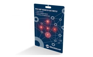
The IoT Sensor Badge is a sleek little promo board featuring the latest PIC16F18345 microcontrollers, a BLE module, five NeoPixel LEDs, an accelerometer and a temperature sensor, all powered by a single 1.5V alkaline (AAAA) battery via a small booster circuit.

I have tried in the past to create my own iOS apps in Swift, but that was just an entirely “different” experience. To be frank that was already better then my very first attempts in Objective C,  no more will be said here about THAT …

Enters Pythonista 3 (briefly introduced in the previous post). Here is a brief recount of the few (mostly fun) steps that got me to a fully functional iOS app in minutes:

1- Figuring out the protocol used by the IoT Badge to communicate via Bluetooth Low Energy.

The IoT Badge promo web page contains a  link to a downloadable MPLAB X project (zip) file. Once unzipped and opened in the IDE, it is easy to identify a module called “RN4020.c”. Unfortunately this is NOT where you will find the crucial bits of the BLE interface although, from the initialisation code, it will be revealed that the module is going to be used in MLDP mode! The true core of the communication interface is rather more cryptically hidden in the “interrupt.c” file where in fact all interrupt service routines are found. Hidden within the serial interface (EUSART) ISR lies the section of code we need to understand.

Here each character received (from the BLE module) is compared against a set of three possible ascii values:

        if (RCREG == '%') { //BUTTON1 PRRESS
            PIR0bits.IOCIF = 1;
            IOCBFbits.IOCBF5 = 1;
        }
        if (RCREG == '#') { //BUTTON2 PRRESS
            PIR0bits.IOCIF = 1;
            IOCBFbits.IOCBF7 = 1;
        }

When the ‘%’ or the ‘#’ characters are received a corresponding button press event is “simulated” by triggering manually the Interrupt on (pin) Change mechanism. This is a technique that I would not generally recommend  but appears to be effective.

        if (RCREG == '$') { //Send requested data
            //CalcTEMP9700(); //Get temperature
            Temp9700Read();
            CalcVBattery(); //Get batter voltage
            TRISCbits.TRISC4 = 0; //NCO on
            NCO1INCL = 10;

            sprintf(s, "@%d, %d, %d, %d, %d, %d, %d, %d, %d, %d, %d, %d, %d, %d, %d, ", G1, R1, B1, G2, R2, B2, G3, R3, B3, G4, R4, B4, G5, R5, B5); //LED data
            USARTWriteString(s);
            sprintf(s, "%d, %d, %d, %d\r\n", (int8_t) Roll, (int8_t) Pitch, (int8_t) TEMP_F, BATTV); //XYZ, TEMP & BAT
            USARTWriteString(s);

If a ‘$’ character is received instead, the device is immediately launching in a sequence of calls to update the temperature and battery voltage readings. Eventually a long string is sent back to the BLE module containing in the order:

  • The ‘@’ character
  • 5x NeoPixel color coordinates as Green, Red, Blue triplets
  • The last (cached) value of the Roll and Pitch angles (in degrees) computed from the accelerometer last reading
  • The temperature, in degrees Fahrenheit
  • The battery voltage, in hundreds of a Volt
  • A Carriage Return and a New Line (‘/r’, ‘/n’) pair terminate the string

All values are sent as decimal and are comma and space separated! This makes for a long but humanly readable format, although not exactly a compact or easily parseable one. The choice to make the temperature and battery voltage calculations in addition to the long string formatting and transmission, “inside” an interrupt routine is particularly troublesome to me. Although it is not the only issue I would have with the code exposed in this project,  it is beyond the point of this post, so we’ll gladly move to the next step.

2- Figuring out how MLDP works

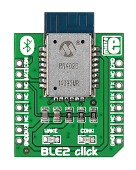
MLDP is the solution that Microchip offers to embedded developers (like me) who are looking for a quick way to emulate a serial point-to-point connection over BLE. In the original  Bluetooth standard, the Serial Profile was offering this feature out of the box. With BLE, the old profiles are gone and replaced instead by the GATT, a very flexible (and power efficient) way to define and handle data transfer via the sharing and remote update of “characteristics”. MLDP brings back the simplicity of the Serial Profile to BLE by offering an alternate mode of communication between the BLE module (RN4020 for example) and a microcontroller serial port (UART). Once the BLE module enters MLDP mode, all other details of the BLE protocol are abstracted away and as soon as a connection is established with a paired device, full bidirectional serial communication is established. Except finding out which characteristics (and service) is being used by MLDP to perform the trick requires a bit of hacking. The official documentation is careful to avoid such details to maintain the full abstraction. But using MCHP own tools (such as the Bluetooth Smart Data application or the the Smart Discover application, both available on the Apple Store)  it is quite easy to figure out the (long) UUID published  for the MLDP service and its data characteristic.

MLDP_SERVICE   = '00035B03-58E6-07DD-021A-08123A000300' 
MLDP_DATA      = '00035B03-58E6-07DD-021A-08123A000301'

Armed with this information we can now proceed to create our Python script.

3- Exploring Pythonista 3 –  Core Bluetooth module

The Core Bluetooth module (or simply ‘cb’) wraps nicely the functionality of the iOS BLE framework and its documentation includes two very useful  example projects interfacing to   similar embedded control boards.

All the  logic can be encapsulated in a single “class” whose methods will be used as  “delegate functions” for each step of a BLE connection process.

class MLDPManager (object):
    def __init__(self):
        self.peripheral = None
        self.buffer = ''

    def did_discover_peripheral(self, p):
      
    def did_discover_services(self, p, error):

    def did_discover_characteristics(self, s, error):

These  “delegate functions” (or callbacks in embedded lingo)  will ensure that we can find and connect with the ‘IoT Sensor Badge’ and the MLDP service/characteristic.

For example, once a service is “discovered”, we can compare its UUID with that of the MLDP_SERVICE found above, and immediately launch the search for the DATA characteristic:

    def did_discover_services(self, p, error):
        for s in p.services:
            if s.uuid == MLDP_SERVICE:
                p.discover_characteristics(s)

Similarly once the DATA characteristic is found, we can enable the ‘notification’ feature and store the resulting ‘handle’ (data_char)  for later use during the communication data transfer phases:

   def did_discover_characteristics(self, s, error):
        for c in s.characteristics:
          if '301' in c.uuid:
              self.data_char = c
              # Enable notification for MLDP input:
              self.peripheral.set_notify_value(c, True)

4- Sending and receiving data with MLDP

Sending data (or a command) to the “other” side of the MLDP connection (the IoT Sensor Badge) is now possible by simply writing  a new value to the DATA characteristic:

    def send_cmd(self, cmd):
        if self.peripheral:
          self.peripheral.write_characteristic_value(self.data_char, cmd, True)

When the IoT Sensor Badge is sending us new data (a bytearray) we will receive  notifications, that is, our did_update_value delegate (callback) will be invoked:

    def did_update_value(self, c, error):
        self.buffer += c.value.decode('ascii')
        #print(c.value)
        if self.buffer[-1] in '\n':
          if self.buffer and self.buffer[0] == '@':
            print(self.buffer[1:]) # send to console
            self.buffer = ''
            self.send_cmd(b'$') # ask immediately for more...

Since the BLE protocol allows each characteristic to pass a maximum of 20 characters (bytes) at a time, the update delegate must perform a bit of buffering in order to re-assemble the longer strings the IoT Sensor is sure to send us.

5- A simple Console Interface

Pythonista 3 introduces a simple Console View for the iOS applications to provide a quick and dirty way to present data (and receive inputs) from the user without necessarily require a complete GUI to be defined.

A few lines of code will give us a quick way to test the code developed this far:

mngr = MLDPManager()
cb.set_central_delegate(mngr)
cb.scan_for_peripherals()
while not mngr.peripheral: 
  pass
mngr.send_cmd(b'$')

This code  launches the Bluetooth core manager waits for the connection to be established with the first IoT Sensor Badge found and the starts the process of continuous update by sending a first ‘$’ command.

The process will continue indefinitely as in a loop as the last line of the did_update_value delegate (callback) is sure to trigger the next request for data…

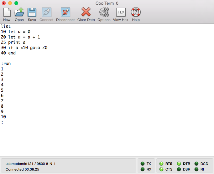
This will quickly fill your iPad/iPhone screen with the strings sent by the IoT Sensor.

Soon  you will want to stop the script (use the little button at the top right of the console view)   and inspect the data. Next, if you are like me, you will itch to create a bit of a UI for the application.

But that is a completely new adventure, which we’ll cover in the next part … stay tuned!

Posted in PIC16, Python | Tagged , , , , , , , | Comments Off on IoT Sensor Badge BLE interface with Pythonista 3

Pythonista 3

Pythonista3Pythonista3  is simply the most fun and easiest/fastest way to develop  iPad/iPhone apps/demos (in Python) to complement your IoT demos and projects.

Apparently the app has been in the Apple Store for more than three years and the author has had time to refine the product and create quite a complete and powerful set of libraries including not only the usual “batteries” that come with Python, but also popular scientific libraries (such as Numpy and Matplotlib) and a set of brand new ones to support native iOS development.

The UI library for example wraps most of the Apple frameworks in such a Pythonic way that it becomes a real pleasure to use. Coupled with a (builtin)  UI editor, it makes defining the user interface for an application a breeze, in stark contrast to the often frustrating experience of using Swift and the official XCODE tools. (Apple might even learn a thing or two from the nicely animated auto-layout helper features of the Pythonista UI editor).

Using the iPad Bluetooth LE interface, is an equally exhilarating experience. The documentation provided is well integrated with the IDE and the code examples are immediately usable and easily customised.

Just when I was starting to wonder if  Apple had not lost its evil grip on the iOS toolchain (you can launch Pythonista scripts from the home screen, create extensions for other applications to call into, share data with the innermost parts of the OS), I run head first into one of the walls built to isolate this beautiful garden: getting code (scripts) in and out of an iPad is still quite a difficult proposition. Mind it is not impossible, using Dropbox and eventually by copying and pasting small bootstrapping scripts it is even possible to share your  Python code on GitHub, it is just so much harder than it needs be or at least compared to the rest of the Pythonista experience. I guess some kind of a price they had to pay to let Apple feel still in control or at least to relegate  Python to a much more limited role than the official toolchain?!

Regardless, this tool is a real life saver (as in “saving many hours of my life”). As much as I liked (mostly) learning Swift, I find Python to be much more effective, for my purposes at least. As a test, I have developed a UI for the IoT Sensor badge IoT_Sensor_Demo_small

The little (credit card sized) board comes with an Android app that connects to it via BLE but iPhone and iPad users were left out to dry.  Here is a link to the GitHub repository for my interpretation of the UI (developed using Pythonista3).

More on the details of the solution in the next post(s).


Posted in Languages, PIC16, Python, Tips and Tricks, Tools | Tagged , , , , | Comments Off on Pythonista 3

In 10 Lines of Code

“In 10 Lines of Code: Rapid Development using Cloud Tools for Embedded Control”.

10Lines It has been another very intense season, so much that I barely had time to make a proper announcement of my new book: “In 10 Lines of Code”, (Lulu, 2016) after all the effort I put into it…

This is really meant to be a complement to the “Rocket Science” book I published last year. In fact while the Rocket book was all about the “why” of the new Core Independent Peripherals, many wrote to me asking for more examples and “hands-on” demonstrations of the CIPs use and benefits. The launch of the MPLAB Xpress online IDE gave me the perfect opportunity to combine the ease of use of the new cloud toolchain (and a new board) with the Core Independent Peripherals. So I set off  preparing 15 new projects carefully chosen to bring the reader step by step up a gentle learning curve.

Thanks to the MPLAB Code Configurator (online), as the title says, all the code examples require the reader to work through a maximum of 10 lines of code. Although, I will be honest, for some of the examples projects you will quickly realise how the fun has just began and you will want to type a few more…

When I published the book on Lulu (in April), I posted all the source codes on Github and then started adding them gradually to the MPLAB Xpress Examples repository. While the book eventually ended up listing 20 projects, I kept developing more as time went by, so stay tuned as eventually a few more “bonus” ones will end up spilling in these blog pages.

Also, I really tried hard to keep the cost of the book as low as possible (limiting it to a max of 150 pages this time, if you now how hard it is for me to keep my writing short and focused …) and due to my son’s pressure I resolved to select a more echo friendly choice of paper (less whitening chemicals). I hope you will appreciate my efforts too!


Posted in PIC16, Tips and Tricks | Tagged , , , , , , | Comments Off on In 10 Lines of Code

PIC16F188xx Pearls

pearlLooking deeper inside the PIC16F18855  datasheet [link] I found out a couple of interesting new things that deserve your attention:

  1. A new Constant Current Output Control for the I/O pins
  2. Memory models up to 32k words (equiv to 64K bytes of Flash) and 4K bytes of RAM!
  3. The list of Core Independent Peripherals is practically complete. Every CIP that has been introduced in the last 3 years is available on this family(!) quantities might vary with the model size and pin out obviously…

Constant Current Output Control

Frankly, the new Constant Current Output control feature is perhaps the most intriguing of the lot. In short, you get to decide what is the output current that I/O pins (participating) will produce among 4 possible values: 1 mA, 2 mA, 5 mA and 10 mA. You also get to decide if the feature applies to sourcing current (output logic 1) and/or synching current (output logic 0). Any I/O pin can be included in the scheme, regardless of its assignment to analog and digital  or any number of peripheral functions.

While there is a single setting for all pins (selected) and the resolution is so coarse, I can see a huge number of possible applications to be explored for this new mechanism. Among them:

  1. General EMI reduction, this goes beyond the slew rate control (per pin) as it potentially limits the amount of noise on the supply lines.
  2. Component (BOM) reduction, as a large number of series limiting resistors could be spared. While the cost of an SMD resistor today is probably close to a milli-dollar,  it is the pick and place time that can add up quickly…
  3. Driving 7-segment / LED displays, combining the constant current outputs with a pair of 100mA strength pins (yes, you get two of those too), without using any external components outside the LED themselves
  4. Linear ramp (capacitor charge time) applications, in combination with the comparators and the voltage reference (+DAC) available on board
  5. … your inputs here…

What I found amazing is that all of the above is available in addition to the PPS feature (the ability to connect any peripheral input/output to any digital I/O) and completely independently of the (very) wide analog multiplexers that make almost every pin of these devices an available ADC input (and/or Comparator input).

The feature is also power supply independent and will work equally nice in a very wide range from 1.8V to 5.5V although, as you would expect, with a proportionally wide linearity zone as the external load applied varies. To that end, I have been shown some preliminary data that looked excellent, but only with time a full set of characterisation data will be collected and eventually complete curves will be posted on the final datasheet (this process has typically required upwards of 9 to 12 months from release of the product, so don’t hold your breath!).

 64K Flash

Frankly it was time for the PIC16 to graduate to the full addressing range of a typical 8-bit architecture. The PIC18 architecture still keeps the advantage with 128K byte models in production (for more than 10 years), but all applications are growing nowadays, especially when there is a communication protocol involved, and this expansion gives the latest PIC16 generation more room to breathe.

To me it is the 4K bytes of RAM though that represents the most interesting development. I am always short of RAM, weather it is to hold a VGA display buffer, a double buffer for a WAV player or program space for a BASIC interpreter

Ok, those are NOT typical applications for an 8-bit microcontroller, but they were certainly more fun to develop because of the challenges they posed.

I am sure you will find true reasons to appreciate all the extra room…

P.S.: I will need to start preparing a second edition of the Rocket Science book now to include CCIO and ADC2

Also see my previous post introducing the PIC16F188xx family [link]

Posted in PIC16 | Tagged , , , , | Comments Off on PIC16F188xx Pearls

Flying the Dolomites


November can be an incredible month for flying the Italian Alps…
IMG_5301 IMG_5327 IMG_5339

Batteries recharged, no further comments required!

Posted in Flying | Tagged | Comments Off on Flying the Dolomites

First Look at the PIC16F188xx family

PIC16F188xx

Back in August a press release announced the imminent launch of the new PIC16F188xx family [link]. This was bundled with another similar launch for the PIC16F157x family that I have reviewed with a tiny bit more detail in this previous post [link].

Today, I  received the first copy of the full (while still preliminary) data sheet of the first two members of the family: the PIC16F18855 – 28 pin model, and PIC16F18875 – 40 pin model, both with 8k words, 16k bytes of Flash memory. (The family will eventually include models up to 32k words or 64k bytes Flash memory size!)

As was the case for the previous family launch, I feel the press release has not been doing justice to these parts, too little detail, too generic a message, invariably designed to impress investors rather than designers…

Here some more juicy details distilled from a first pass through the data (sheet):

  1. The part number choice (188) for this family is one of those rare ones where there seems to be a logic (at least to me), and if you follow me through the next few lines, you will hopefully agree with me too: these parts are at the same time an extension of the (very) successful PIC16F182x family (small pin count + communication) and a remake of the glorious  PIC16F88x family (28/40 pin featured in countless articles/books/courses) with which they remain pin to pin and feature by feature compatible. Merge the two prefixes and voila’…
  2. Being part of the  PIC16F1 generation means primarily that they feature the very latest evolution of the PIC16 core (Enhanced Mid Range is the official name) which offers a linear addressing mode for RAM access and improves considerably the performance of C compilers.
  3. As all recent additions to the PIC16F1 family they also get a load of  Core Independent Peripherals (CIPs), among which:  CLC, NCO, CRC/SCAN, DSM, PPS, CWG. (see the Rocket Science book for more on these)
  4. They also introduce three innovations of their own:
    1. A new 10-bit Analog to Digital Converter with Computation (named ADC2, read ‘ADC-squared’).
    2. Two new low power modes, IDLE and DOZE, borrowed from the PIC18 and larger (PIC24/PIC32) families, but never before seen on a PIC16 class device. These expand the granularity of the low power modes possible and adds interesting new tools for the extreme low power designers.
    3. A Peripheral Module Disable  (PMD) unit that allows to disconnect completely any unused peripheral from the clock tree of the device, with a measurable additional power saving for XLP applications. This was also adopted before on PIC18 device, but never seen on PIC16 families.

So B) and C) are not really new-new, it is more a matter of showing how the PIC16 and PIC18 families are converging and  borrowing from each other the best features introduced in the last few years (CIPs, XLP).

ADC-squared

The ADC2 deserves some more careful analysis as it promises to be another breakthrough advancement of the Core Independent Philosophy.

The intuition that all peripherals should be connectable directly and capable of performing their functions as independently from the core as possible.

Core Independent Peripheral can be configured and assembled to form complete functions  that reduce the core workload, reduce the required clock speed, and eventually reduce code complexity and/or power consumption.

To this end the Computation part (the second C) in the new module, is where things get really interesting. Continue reading

Posted in PIC16 | Tagged , , | Comments Off on First Look at the PIC16F188xx family

Saleae Logic Analyzer

saleae

Saleae Logic Analyzers stand to similar (low cost- USB) products as an iPhone stands to an old Nokia soap-bar. And it is not just a matter of (modern) looks, although they decidedly aim at an Apple-ish look and perhaps beyond. It’s the software that comes with that sets them apart. Also it is important to note that they run seamlessly on all platforms (Windows, Mac and Linux) which in my case means that the (very) last umbilical cord between me and Windows has now been rescinded!

With the combination of low prices and ease of use, there are practically no more excuse not to keep a little logic analyser on your desk. Whether it is for debugging a simple serial port issue, an I2C bus conflict or a complex timing issue (with the VGA emulation?)  a small logic analyser can eliminate long hours of guesswork and trial and error better than most/any scope for a minuscule fraction of the money.

Highly recommended!

Posted in PIC32, Tools | Tagged , , , | Comments Off on Saleae Logic Analyzer

Tiny Basic for Curiosity

TB Screenshot

Watching a retro Basic interpreter running on a modern MCU is somewhat poetic to me…

Even better if the Basic interpreter is in its turn running on top of a (retro) Virtual Machine as is the case of the TinyBasic implementation of Tom Pittman [link] circa 1976!

Even after compiling both with a current version of a C compiler (XC8) and using MCC (to generate the serial port routines) the resulting code is minuscole (approx 6kB) and fits well on a PIC16F1619 on a PICDEM Curiosity board.

I added the project to the Rocket collection and made it available on GitHub.

(If you like virtual (machines that is) you might also enjoy [link])

Posted in Languages, PIC16 | Tagged , , , , | Comments Off on Tiny Basic for Curiosity

Learning Bluetooth LE with the BLE2 Click

BLE2-Click

Playing with the Bluetooth Low Energy Click board (BLE2 based on the RN4020) on a Curiosity board is a fun way to get acquainted with this technology. My first humble step was to get the simplest example offered in the RN4020 PICTail (one of the earliest demo boards available for evaluation of the little radio module) user guide and port it over with minor modifications to my new hardware setup.

Using the MCC, I performed the following simple initialisations:

  • SYSTEM: 16MHz, MCLR ENABLED, LVP ENABLED
  • GPIOs: CMD on RC5 (out), WAKE_SW on RA4(out), CONN on RC2 (in)
  • TMR2: 4ms period
  • ADC:  channel POT on RC0, left aligned, ~40k smps
  • EUSART: Asynchronous 115,200 baud, 8-bit, none, stdio redirect

And voila’ the application was created and ready for me to fill in the main() function.

I added an initialisation of the RN4020 module:

 // initialize RN4020
 WAKE_SW_SetHigh(); // enter command mode
 mygets();
 sendCMD( "SF,1");        // factory reset
 sendCMD( "SS,C0000000"); // enable DeviceInformation and batter 
 sendCMD( "SR,00000000"); // act as a peripheral
 sendCMD( "S-,Curiosity");// change name
 sendCMD( "R,1");         // reboot with new settings
 mygets();
 __delay_ms( cmdLONGDELAY); // wait for CMD prompt
 sendCMD( "A");           // start advertising
 while( !CONN_GetValue());// wait for a connection

Followed by  a very simple main loop:

   while (1) {
        uint8_t time;
        // time is measured in multiples of TMR2 period (4ms)
        if ( TMR2_HasOverflowOccured()) { 
            time++;
        }
        if ( time >= 50)   // 200ms
        {  
            uint8_t battery =  ADC1_GetConversion( POT)>>9;
            time = 0;
            // update the battery level characteristic
            printf( "SHW,0018,%02x\n", 
                    (battery>100)? 100: battery); 
            mygets();          
        }
    }

Notice how this demo does not use the MLDP mode – which emulates a sort of Serial profile similar to the (RN41) Standard Bluetooth module – which would have felt like cheating here. (See my previous project using the RN41 Bluetooth Click [link])

My intention is to learn how to define GATT Services and Characteristics and make full use of the BLE proper features.

You will find the new BLE-Battery project added to the Curiosity Rocket repository on GitHub [link].

Also I can strongly recommend the following applications, for iPhone and iPad users:

For Android smart phone, users:  Android App Demo

To be continued…

Posted in PIC16 | Tagged , , , , , | Comments Off on Learning Bluetooth LE with the BLE2 Click

mruby

mruby_logo_red_icon

mruby is a lightweight implementation of the Ruby language designed to be linked and embedded into other applications. It is a branch of the original project initiated by the same author Yukihiro Matsumoto (a.k.a. Matz) and a strong international team of contributors. There are several reasons to be enthusiastic about this development even  for us embedded control developers (spoiler alert, see #4 and #5):

  1. It introduces the possibility to create single file executables for Ruby applications. This can reduce considerably the (deployment/distribution) headaches due to library dependencies common to traditional Ruby (but also Python, Java …) projects. All the necessary modules for an application can be compiled (to byte codes) and shipped without the need to include source files and without having to handle large folder trees comprising several tens (or hundreds) of individual files.
  2. The ability to produce byte codes (files) is also new to Ruby, although it had been used extensively in other languages (Java, Python…) before.
  3. Taking a  lesson from LUA (eLua project), mruby can now be easily launched from inside a C/C++ application. A script can be passed as a text file to the compiler/interpreter or as a byte code (array) directly to the interpreter. The latter is the mechanism that allows a single file executable model as per #1.
  4. Most importantly for us embedded control developers, mruby has gone on a strong diet. Many of the builtin (system) services and features have now been re-factored outside the mruby core and can be re-introduced (if needed) by accessing individual library modules.
  5. As a consequence, the interpreter is now much reduced in size and can be cross compiled for low cost 32-bit microcontrollers including …. the PIC32 (MX7)! The official repository on GitHub contains already examples for a few embedded platforms including the chipKIT MAX32!


Posted in Languages, PIC32 | Tagged , , , , , | Comments Off on mruby