
Introduction
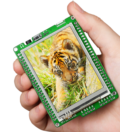
PIC32 Mikromedia boards replace the original PIC24 microcontroller with a larger and faster model of the PIC32 MX4 series: the PIC32MX460F512L which is pin to pin compatible but >8x faster (up to 100MIPS) and with 2x the Flash memory and RAM. Most all other features of the Mikromedia board were left unchanged providing for an excellent compatibility out of the box and a nice (upward) migration path.
Source code
A Github repository with all the projects and exercises offered in the book ported and ready to load and execute on the PIC32 boards.
Porting Notes, Tips and Tricks
Often the journey is more interesting than the destination, here a short summary of the steps (forward and occasionally backward) I took and the notes I made along the way.
First Things First
The first step when porting an MLA project to a new hardware configuration is to update the HardwareProfile.h file.
Although the PIC32MX4 family was designed from the very beginning to be almost a drop in replacement for the PIC24GB micro controller family, the MikroElektronika designers have wisely opted to take advantage of the extra performance of the PIC32 to gain graphics speed. In fact the TFT display is now connected to the PIC32 via a 16-bit wide bus (using the PMP in x16 mode) and a few of the I/O pins have been shuffled around to make room for it. Among them the SD_CD and SD_WE signals have changed port assignments, most all of the MP3 decoder I/Os as well, but the one change that has the most impact of all (all previous are simply covered by simple HardwareProfile.h edits) is the one affecting the display backlight which is re-assigned to the PORTA pin 9. The importance of this change is due to the fact that this control signal used to be conveniently placed on top of a PWM output (OC1) (multiplexed on pin D2), and from there it could be used to “dim” the display. This will have to be taken care of differently now (see Chapter 7 below).
Chapter 1. Hello World
In this first exercise the micro controller configuration is generated for the first time (using MPLAB X Configuration bit window) and later copied to the PICConfig.h file. The peripheral clock of the device is tested simply (blinking the display backlight) to verify the assumed processor clock speed. A default setting of 80MHz for the System Clock can be easily configured and a leisurely 40MHz peripheral clock is derived from it. Note that while the peripheral clock could be pushed to 80MHz as well, this would have had little or no practical impact on the following exercises as most other devices on the Mikromedia board (SD card, MP3 decoder) cannot operate at such speeds and would have required larger pre-scaling factors.
The solution to the Chapter 1 challenge is in itself a great test for the compatibility of the peripheral libraries of the PIC24 and PIC32 families. Which is actually quite poor in some corner cases, such as the rtcc.h module (accessed via the general #include “plib.h” on the PIC32), despite the almost absolute identity of the hardware RTCC module present on chip.
The PIC32 rtcc.h library module insists on using long unsigned integers to pass to and from the library routines where the PIC24 library used structures and pointers just as efficiently. Also for reasons I could not fathom, the PIC32 lib authors decided to replace all the RtccWriteXXX() and RtccReadXXX() functions with RtccGetXXX() and RtccSetXXX() calls. Similarly arbitrary seem the changes to RtccInit(), which used to be RtccInitClock(), and RtccEnable() in place of RtccOn().
A second area where the differences between the two architectures (PIC24 and PIC32) are unnecessarily amplified is the Power Management. A PIC32 must be sent to “sleep” using the call PowerSaveSleep()!
The end result is an almost complete re-write of the few lines of code required to use the RTCC module to blink the display backlight while saving a few precious milliAmpere.
Chapter 2.Hello MLA
No changes required.
Chapter 3. Graphic Resources
Beside invoking the Graphic Resource Converter (GRC) with the XC32 setting and regenerating the resource.c files, no changes were required.
Chapter 4. Touch
In this Chapter Timer3 is used to define the periodic interrupt call to the touchscreen state machine. Interrupts on the PIC32 require a slightly different use of pragmas as the system needs to take into account a user defined priority for each vector and need to specify the optional use of a shadow register set (a great performance feature). As a result the code inserted in the uMedia.c support module is slightly modified. Also, it is in the uMBInit() function that we will add a few instructions required to optimise the PIC32 cache memory, select multi-vectored interrupt mode for maximum performance and other minor house keeping task (such as disabling the optional JTAG interface etc.).
Chapter 5. Storage
No changes required. Both the File System library and the Serial Flash support module make a good job of supporting the PIC32 (SPI) interface although with widely different approaches.
Chapter 6. Sound
Despite the almost identical nature of the SPI peripheral module between the PIC24 and the PIC32 architecture, the PIC32 peripheral library is missing some of the low level symbols commonly used in PIC24 “bare metal” applications (SPI2CONbits.xxx). This forces the designer to make a wider use of the more abstract calls (such as OpenSPI()). While this was expected to add readability and portability to the project it turns out that the thin layer of abstraction provided was in reality masquerading dangerously an important detail. In fact OpenSPI() takes two arguments that are simply the two values written to the SPICONx registers. It is actually easy to miss the fact that the prescalers (primary and secondary) of the SPI module are replaced entirely by a single new entity controlled by a separate register which is NOT initialised by the OpenSPI() call! It is instead necessary to write separately to the BAUDRGx register to affect the device bit rate.
In the last project 6.4 , interrupt driven sound playback was an opportunity to integrate three services that eventually depend on a periodic interrupt call: the touch state machine, a sound callback and a backlight dimming software PWM implementation (that will be exploited in the following chapter).
Chapter 7. Graphics Object Library
The first two projects are ported with no modification save for the software supported dimming of the display backlight.
The second two projects depend on Graphic Display Designer tool support of the PIC32 mikromedia specifics. This is still being investigated at the time of this writing.
Chapter 8. USB
Both CDC and HID class projects work right out of the box without modification.
Bonus Projects
The Pond project required no modifications.
Just as the first exercise in Chapter 1, the Alarm project fell victim of the extreme incompatibility between the two Rtcc.h peripheral libraries. In this case the largest source of edits proved to be the re-definition of the rtccTime and rtccDate structures with the introduction of unnamed-union members in the PIC32 version. (Time->f.hours became Time->hours…)
Summary
The PIC32 brings some serious MIPS to the Mikromedia board (>8x) and faster access to the TFT display controller (2x). Unfortunately the great hardware compatibility offered by the PIC32 architecture is buried and eventually negated by the different peripheral libraries.
The MLA does a great job of elevating us from such differences, though it is still up to us to complete the abstraction as much as possible with a customised set of board support modules.


Pingback: Adding Support for the PIC32 Mikromedia | Pilot's Logbook
Pingback: Microcontroller Core Simulation Strategies | Pilot's Logbook