The Big I2C SEE Table

Not all I2C Serial EEPROMs are created equal. In fact there is a lot of variety out there as the memory size increases the addressing schemes change, the number and use of the device select pins change as well. The size increase reflects more or less closely the passing of time (years) and with it the evolution of the market of serial EEPROMs within and beyond the confines of the original specifications of the bus.

To be able to adapt the code developed in the previous postings, you will need to pay close attention to the details. To simplify the task, I have tried to collect in one big table the key elements that differentiate each device.
Continue reading

Posted in I2C | Comments Off on The Big I2C SEE Table

I2C Interface to Serial EEPROMS (continued)

In a few previous postings we started exploring the I2C interface and in particular its use to access the most common and inexpensive type of Serial EEPROMs (24xxx). After the long preamble, it is about time to start talking about code. Today we will write a set of functions to read and write 16-bit integers to and from a Serial EEPROM device (a 24LC16 to be precise) similarly to what we have done in chapter 7 with the SPI interface to the 25lc256 device. Continue reading

Posted in I2C | Comments Off on I2C Interface to Serial EEPROMS (continued)

KTUS

This past weekend I found another perfectly good excuse to spend a Saturday flying across Arizona. Ivan, a friend from the old continent, sent me an email during the week, he was in Arizona for company training but stuck without a car in Tucson for the weekend. Could we meet? And when a friend calls, how can you not listen?

The trip by car would have been a couple of hours (each way) of absolute boredom driving across the desert for hundreds of miles assuming perfect traffic conditions (an improbable assumption on this stretch of highway). By airplane, it would have been less than 50 minutes. There were no doubts in my mind on which way to go except for the weather. A cold front was supposed to cross the state right that day. Precipitation was not part of the picture, this is Arizona after all, but a fair amount of wind (variable direction and gusting to 25knots) was showing in the Terminal Area Forecasts (TAFs) on Friday night. Saturday morning, an update showed that the front was late and would have crossed Arizona only in the afternoon and off I went to beat the wind and reach Tucson by air.

Tucson

Continue reading

Posted in Flying | Tagged | Comments Off on KTUS

I2C Interface to Serial EEPROMs (continued)

In two previous postings (Chapter 7 1/2, I2C Interface) we have started looking into the I2C interface, some of its applications and the very basics of the communication protocol.

It’s time to start sending and receiving data bytes and learn how to form commands to communicate with what is perhaps the most common type of device requiring an I2C interface: the Serial EEPROM (SEE for short). Continue reading

Posted in I2C | 1 Comment

Of Explorer 16 boards and 5V LCD displays…

I read with interest today an errata for the Explorer16 demonstration board…

I know, it seems strange to think of an errata for a demonstration board, but it can happen and as in this case, there is a good lesson to learn for all of us, living the dangerous lives of the Embedded Control designers on the edge between 5V legacy technology and the new 3V generations of products.

In order to keep their options as open as possible, the Explorer16 designers arranged for a number of different LCD displays to be used alternatively on the board. Three different layouts were pre-wired and, depending on market conditions (price) and availability, one of several different models of LCD displays (from different manufacturers) will be mounted at any given point in time. Since they are all compatible (or I should say there is a common minimum denominator among all of them) there are virtually no changes required to the demos and code offered with the board.
Interestingly some of these LCD displays are 5V and some are 3V devices. Since most of the PIC24 digital I/O pins are 5V tolerant, theoretically the two technology can be alternated without consequences except for one case that was recently uncovered.

When the Lumex™ LCM-S01602DTR/M module was used (the errata document will teach you how to recognize it) things got more complicated. This 5V LCD module has internal pull-up resistors connected to the 5V rail. When the PIC24 I/Os connected to it (for example PMPA0 which is multiplexed with the AN15 analog input function) is left three stated (very high impedence) it will let 5V get inside the PIC24!

Notice that this will not necessarily damage the part (the pull ups are pretty weak after all), but it will produce a more subtle problem, it will skew the internal analog voltage references and produce a large offset on the A/D module readings for example.

Reading the errata carefully, you will realize how an essential part of the problem is the high impedence of the input pins once three stated, which produces, with the LCD internal pull ups, a partition with a very high output voltage (close to 5V).

Decreasing the impedence, by turning pins to outputs (as you do when you enable the PMP), or by adding pull down resistors (even if of relatively high values) solves the problem as the partition is modified to produce a lower voltage …

The lesson learned: Once more, make sure that when you interface to a 5V device you either:

  • use exclusively pins that are pure digital inputs (5V tolerant)
  • use open drain outputs if you want to swing a 5V signal

Watch out from all pins that are multiplexed with analog functions, even if you have the analog function disabled in your particular configuration.

The pin-out cross reference table published in the previous posting “The Missing Pinout Table” might help you double check…

Posted in Tips and Tricks, Tools | 1 Comment

I2C Interface (continued)

The I2C bus is based on a very simple protocol, a small set of rules that dictate how the two lines SDA and SCL are supposed to operate to allow the transfer of data.

With the premise that, at idle, both lines are high (pull up):
Rule 1) During the transfer of a bit, the SDA line can change status only when the SCL line is low.
Rule 2) When the SCL line is high, the SDA line status indicates the value of a bit.

Two exceptions to the above rules create special conditions that are used to delimit the beginning and end of each “transaction” between two devices on the bus.

A START condition is indicated when (in violation of rule 1) the SDA line changes from high to low while SCL is high.

A STOP condition is indicated when (again in violation of rule 1) the SDA line changes from low to high while SCL is high.

The figure below extracted from a typical device datasheet is worth a million words.

i2c sequence Continue reading

Posted in I2C | 1 Comment

Chapter 7-1/2 The I2C Interface

Over the last year I have received a couple of emails from readers inquiring about the absence of examples on the use of the I2C(tm) synchronous serial ports of the PIC24. I imagine many more of you would have liked to ask the same or at least might have wondered why the omission.

I have to make the premise that it was never my intention to write the “definitive guide” to the PIC24… there are already too many books that start with that claim (often in the title) and fall (way) short or end up basically rephrasing the entire device datasheet. So I set my goal to provide meaningful/entertaining examples on as many features of the PIC24 architecture as I could fit in 300 pages (you will notice that I ended up with almost 400 pages, and that was after the publisher got mad at me and had to reduce the font size twice…)

I also set my sight on one specific hardware platform: the Explorer16 board, trying to exercise all of the features available and then expand using the small prototyping area or the PICTail(tm) connector.

It just happened so that the I2C port was left behind, although it is briefly introduced in chapter 7 and compared to the other main synchronous option: the SPI port.

This omission is in no way an indication of a lesser importance of the subject to the embedded control programmer, on the contrary, if anything the popularity of the I2C interface is growing in the recent years. This is reflected in the continuous introduction of new devices that are based on or support it, but also new advanced application specific protocols that use I2C as their physical level / transport layer.

Examples of devices recently introduced by Microchip and based on the I2C interface are:

Examples of application specific protocols based on the I2C interface are:

  • SMBus, the System Management Bus, used in personal computers (and servers) for low speed system management applications
  • IPMI, the Intelligent Platform Management Interface, used to monitor the system health and manage (mostly servers) systems remotely.
  • PMBus, the Power Management Bus, used by advanced digitally controlled power supply units to monitor, configure and control power.

The PIC24 datasheet and reference manual provide ample documentation on the I2C peripheral features and options available but I will try and provide a little more perspective and practical advice in this and the next few postings.

The hardware requirements of the generic interface are very simple:

  • A clock line (SCL) is controlled by the Master(s)
  • A data line (SDA) is controlled alternatively by Master and Slave devices
  • Two resistors (typically 2.2k ohm each, but the value will vary with selected speed and voltages) are used to pull up the two open-drain output buffers

That’s all!
To begin with, we should ask ourselves if we truly need to use a peripheral module or if we could do without (like most 8-bit PIC microcontrollers used to do)!? In fact the I2C specifications indicate a range of relatively low bus speeds. The original documentation (published by Philips decades ago) indicated 100kbit/s maximum and even if the more recent updates brought the speed up to 400kbit/s first and more recently to 1Mbit/s this is clearly within the realm of software (bit-banged I/O) solutions.

When we consider the most common application, that sees the PIC microcontroller as the only master addressing a handful of devices (typically 24xx serial EEPROMs) this is definitely an option. The advantage of a software approach is in the freedom it provides to choose any I/O pin we want, and the task is further simplified on the PIC24 since all I/Os can easily be configured for open-drain operation (see ODCx registers).

(Trick: In the single master case, the SCL line control never changes and therefore a common hardware and software simplification includes reducing this line to a standard CMOS output.)

In the good old times, on 8-bit PIC microcontrollers and using only assembly programming, I have seen implementations of I2C (single master) interfaces to serial EEPROMs in as little as 40 instructions (ever heard of the famous “Frank code”!?).

Another common trick used in power constrained applications is that of powering the entire peripheral device off one of the I/Os of the PIC microcontroller. In particular referring again to the common Serial EEPROMs (say a 2kbytes capable 24LC16), you will verify that their power consumption is limited to 3mA max. (even when operating at 400kHz) a value that is well within the capabilities of any PIC24 I/O port.

On Microchip web site you will find several examples of “software” I2C libraries (AN1100 for example) , don’t ignore them just because we have the luxury of having two hardware interfaces on the PIC24Fj128GA series … check all your options first!

(to be continued)

Posted in I2C | 2 Comments

Having Fun Prototyping Lately?

PICTail(tm) Plus is the name that Microchip uses for the expansion socket offered by the Explorer16 boards. It is one of the easiest and most flexible options available for prototyping out there. All the signals from a 100 pin PIC microcontroller are grouped logically and conveniently in three sections so that if only a few signals are required a smaller board can be arranged. The edge of any PCB can be quickly transformed in an inexpensive (as in free) connector as soon as you realize that all it takes is a set of 1mm spaced traces (gold plating is an option you might consider for longevity). NOTE that all connections are clearly documented in the appendix of the Explorer16 User Guide (DS51589) .

The AV16 board that I developed to support the code examples of the book is only one example of PICTail Plus expansion board, on microchiDIRECT you will find many other options to support: IrDA, Graphic displays with touch sensing, Ethernet, SD Cards and more.

But my all times favorite is the simplest one of all: AC164126  also known as the:

Prototype PICTail Plus board 

PICTail

For $20 you get 3 (three) boards actually. All the signals are accessible in a standard spacing four row line up with silk screen call outs. Get your soldering irons warm!

Posted in AV16/32, Tools | 1 Comment

Playing Poker along the Colorado River

Oh the things a pilot would not do just to find an excuse to fly some more!

Well, gambling is one of them! For the fourth year in a row, the last week end of January, a benefit Poker Run was organized by the association of women pilots of Arizona (the 99-ers) and I invited Marc, a colleague and old friend, to fly with me and test his new digital SLR. Jake, another pilot/colleague joined us flying his own, recently acquired, C172.

For those of you who never heard of a Poker Run, a simple explanation is due, at least with regards to the details of the flying version of the event, as they tell me that similar things are common in the boating/sailing world. The organizers pick five locations, airports within a given radius of several hundred miles, in our case in cities along the Colorado river. They establish a beginning and end time. At each of the five locations each pilot can pick a poker card (in a sealed envelope). The location chosen this year where, from South to North:
Blythe, Parker, Lake Havasu, Sun Valley and Needles.

The order the airports are reached is not important as long it is done within the allowed time slot. Each pilot is free to pick the flight path that is optimal considering his place of origin and the capabilities of the aircraft. The last card is typically retrieved in the final destination airport (Lake Havasu in our case) where all participants convene for the cards to be played (opening the sealed envelopes in front of the judges). The highest scores are noted and a small portion of the benefit money gathered with the registrations is used up as a jackpot for the winners.
I had been intrigued by the idea to join the Poker Run for the last couple of years but for one reason or another I had never been able to. This time the weather was perfect and at 5am (well before dawn) we were preflighting the planes at the Chandler municipal airport. Wheels up at 6:30am.

Moon

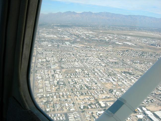
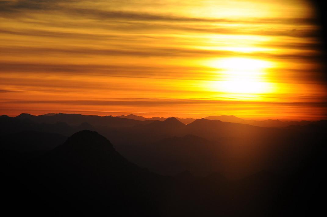
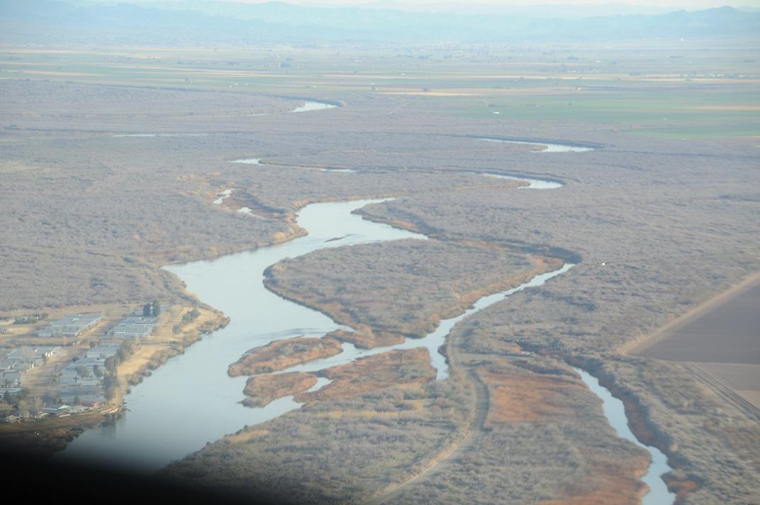
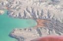
Mark brand new Nikon D300 took some gorgeous pictures throughout the flight although, enthusiastically experimenting with all the new features of the camera, he tried very hard to botch them. When the sun came up, we had already covered a lot of desert and we were almost approaching the edges of the border between Arizona and California marked by the Colorado river.

Dawn

Landing in Blythe, almost exactly at 8am, was easy as the air was still so calm and it seemed like we were the first ones to reach the location. When we made it into the FBO and found it empty, a terrible doubt dawned on us… Was the Run starting at 8am MST (Arizona time) or 8am PST (California time)? The event brochure was not mentioning the detail and coming from Phoenix we had so naively assumed… Were we one hour early? Waiting one hour in an empty airport office in the middle of the desert was not exactly and exciting prospective. Fortunately, after a few minutes of perplexity, a friendly face showed up behind the counter exclaiming “so… is it today?” and offered us a box full of sealed envelopes to pick from…

While taxing back to the runway, a few voices started coming from the radios… we were not alone anymore… other pilots were joining the race…

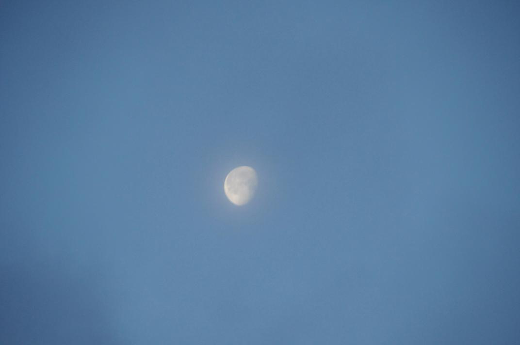
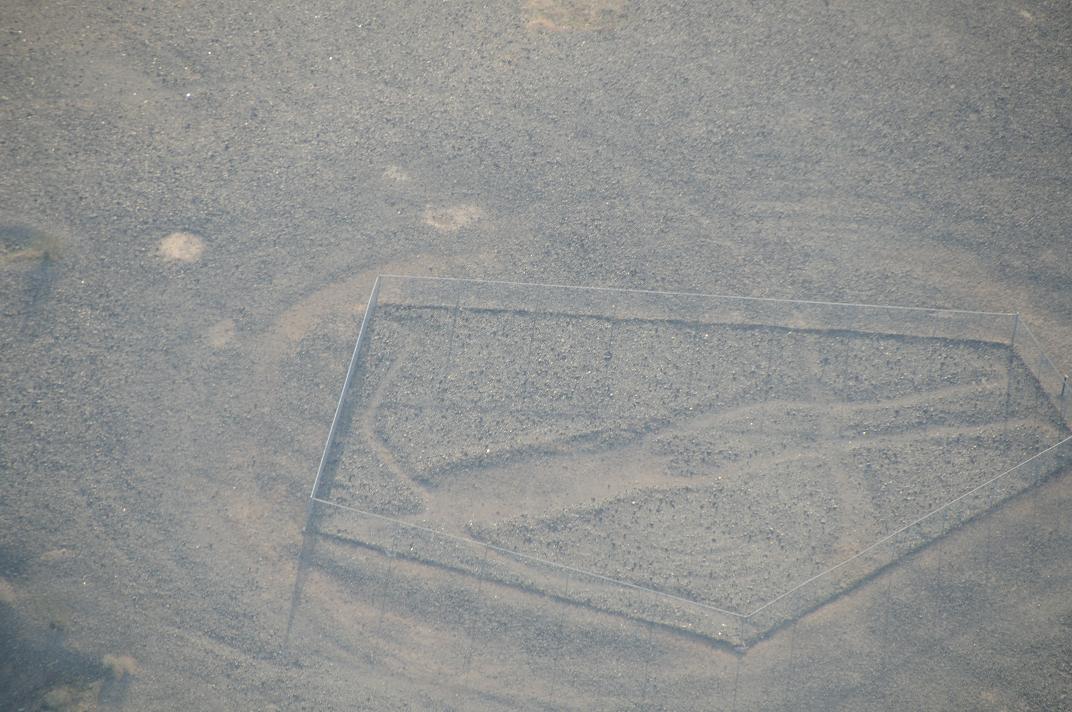
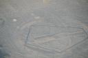
Flying north toward Parker, our next stop, I remembered that there were some interesting indian “paintings” (or I should say carvings) that could be observed only from an airplane as they lay on the flat desert floor. 40-50 feet in size they were meant probably to be seen by some ancient gods. But as we started searching for them we realized that those gods had to have pretty good eyes. As big as they were, when flying anywhere above 500 feet from the ground the images would be too small to be detected against the rugged terrain. Here is just one of the many gorgeous pictures we took…

paintings

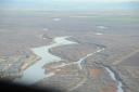
After Parker, we continued up along the river passing Lake Havasu,

Lake Havasu(where we would return later)

and all the way up to Sun Valley, a minuscule airport with such a narrow runway that we struggled to distinguish it from the network of streets of the surrounding developments. Then South again along the river to Needles, where cadets from the local military base handed us the envelopes right to the plane (nice!).

The final short hop back to Lake Havasu things got a bit hectic. All of a sudden the radio was filled with voices from a dozen airplanes all converging to the final airport at about the same time.

Colorado

After a long(!) landing and a quick tie down, we raced to the judges’ counter to see our hand: a king, a queen, a nine, a ten and a… five!

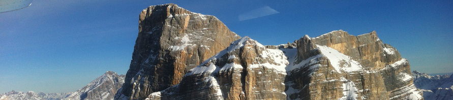
Oh well, we were there for the flying after all. As a bonus the organizers offered an excellent BBQ to all participants and a short technical seminar (on mountain flying) was offered in the afternoon to tempt us and stay longer…

To top the day, the local FBO had the lowest fuel prices to be found in Arizona (and California too). What more can you ask for in a beautiful January day?

Posted in Flying | Tagged | Comments Off on Playing Poker along the Colorado River

The Stack … so misunderstood (continued)

So we understand now what we don’t know (see The Stack … so misunderstood, part 1). We know how to set a minimum limit for the Stack size. We know how to verify how much space the linker has allocated for a project. We DON’T know how much Stack space our project is actually using!

If we have the luxury of being able to simulate the entire application in a complete and realistic scenario, nothing beats the power of MPLAB SIM. We can open the Watch window and keep an eye on WRGE15 and SPLIM. Opening the Stack window we can watch the stack grow and see each function parameters as they are passed along.

But as the complexity of a project grows, full simulations became less likely… and we want to find a way to identify Stack issues at run time when debugging in circuit.

Quite empirically, if a program is not crashing (as in experiencing inexplicable resets) chances are we have not reached the stack limit (yet). But what if we do experience those resets… in a complex application things can go wrong in many ways … it would be nice to be able to pin-point the issue and make a clear determination when we fail because of the stack.
Here is an example project with a (perverse) recursive function (call()) that will exercise the stack available for as many nested calls as the parameter passed: stack.c

Make the parameter large enough or allocate a large enough Heap (8,000?) and sooner rather than later it will produce a Stack Error trap.

By replacing the default trap handler for the _StackError vector, we could perhaps place a function (with an infinite loop) in there to capture and retain control of the application when things go wrong. Placing a breakpoint inside our custom handler we would be immediately alerted as soon as our program reaches the top of the stack space. Here is an example: stack2.c

Unfortunately the new handler, as any C function, is going to need to use the stack itself. Even if we declare it with the no_auto_psv attribute (to avoid saving and restoring the PSV registers values) and even if we don’t use any local variable.

It seems like a catch 22 condition. We cannot write a handler for a Stack Error condition in C because by definition each C function uses at least a small amount of Stack space.

We might be tempted to artificially lower the stack limit (SPLIM) to allow for some extra room for the handler function so to “break the loop”. But this is just an illusion… We cannot know before hand by how much the stack will be exceeded when the trap occurs. In other words, think of a case where the stack is almost all used up, the stack pointer is just one word below the limit and then a function call is made to a routine that allocates 100 bytes for local variables… To get away with it, we should really lower the stack limit for the worst possible case (the function that allocates the largest amount of stack space) but this is exactly the type of complex and manual analysis of a project we were determined NOT to have to go through in the first place (besides a possible big waste of space).

Fortunately to our rescue comes one powerful option of the MPLAB C30 compiler, that allows us to insert custom code before the prologue of an interrupt handler, that is before the stack is touched! It is called the interrupt preprologue. Here is an example of how we would use it, combined with one instruction of inline assembly to achieve a blocking interrupt handler that does not rely on the stack: stack3.c

void __attribute__((no_auto_psv, interrupt( preprologue(“1: bra 1b”))))

where the “1: bra 1b” is a single instruction infinite loop that we insert before the handler prologue.

But by the time we do this and we try to set a breakpoint on the line, we realize that we have gone full circle. This is not C code anymore… and to set the breakpoint we need to switch to the disassembly window…

If we surrender to the evidence, we get a cleaner, less cryptic and overall more elegant solution by using the original code stack.c and including in our project a simple (three lines long) assembly source code:

.global __StackError
__StackError:
bra __StackError

(Note the double underscore before the label StackError)

Save it as stackhandler.s and add it to the project.

Now we can set a breakpoint inside the new handler and we can have our real time debugger to halt and notify us whenever a Stack Error trap is triggered at run time!

Perhaps we learned a good lesson today. Certain things are just meant to be done in assembly! …although there are not that many left anymore!

Posted in Tips and Tricks | 1 Comment